
icibici
here's a £20, open source brain-computer interface you can use with your phone, tablet, laptop...

Project Overview
If your board has a blue screw terminal, check the positive and negative battery terminals: on boards shipped through 2020, these are reversed. Read the hardware instructions, below, carefully before use.
The icibici kit is intended for use for ENGINEERING DEVELOPMENT, DEMONSTRATION, OR EVALUATION PURPOSES ONLY and is not considered by its developers to be a finished end-product fit for general consumer use. Persons handling the product(s) must observe good engineering practice standards; in particular, it must not be used while plugged into a device (e.g. laptop, tablet, phone) that is plugged into the mains to charge.
TL;DR: join the icibici Google Group to plug yourself in.
Motivation
In summer 2016, we met to build a low-cost brain-computer interface that you could plug into your phone. We want everyone interested in BCI technology to be able to try it out.
Two months later, we premiered the world's first £20 BCI at EMF camp as 'smartphone-BCI'. Since then, we have given workshops at Tokyo Hackerspace, London Hackspace, SHA 2017, Bornhack 2018, EMF 2018, and CCC 2019.
As of autumn 2019, we have:
- a simple, one channel EEG kit that amplifies neural signals, and modulates them for input to an audio jack;
- a basic Android diagnostic app;
- a Unity text entry app;
- code from Elad Rapaport's team at the Brain Gurion hackthon.
What we have
The v0.1 circuit reads a bipolar EEG signal and sends the signal out along an audio cable, for use in a smartphone, tablet, laptop, etc.
EEG signals are difficult to work with as they are very faint, and easily interfered with by other signals, including muscle movements and mains electricity - both of which are much more powerful. Also, the interesting frequencies range between 4Hz to 32Hz (depending on the intended use), but a smartphone sound card will filter out all signals below 20Hz.
Thus, the v0.1 circuit:
- amplifies the signals that comes from the electrodes, boosting them from the microvolt to the millivolt range;
- uses amplitude modulation to add a 1kHz carrier tone, allowing the signal to bypass the 20Hz high-pass filter behind the phone's audio jack.
For more details of the circuit, visit the hardware files. The circuit design files are open source: please use them, and improve upon them.
The signal can be used by any software that accepts and uses signals from an audio port. We describe, below, two apps that are in development alongside the hardware. In both cases, frequency analysis is performed on the input signal, to extract the features of the original EEG signal. There is an example of an Android app that does this whole process in repo .
The diagnostic Android app is under development and right now just offers:
- shows the frequency analysis of the EEG signal
- shows how the alpha band power fluctuates over time
- shows a broader frequency analysis that can used as a sanity check for the hardware
The code needs to undergo some refactoring and implement some more cool functionality.
Ryan Lintott has developed a Unity-based SSVEP text-entry app.
The Hardware
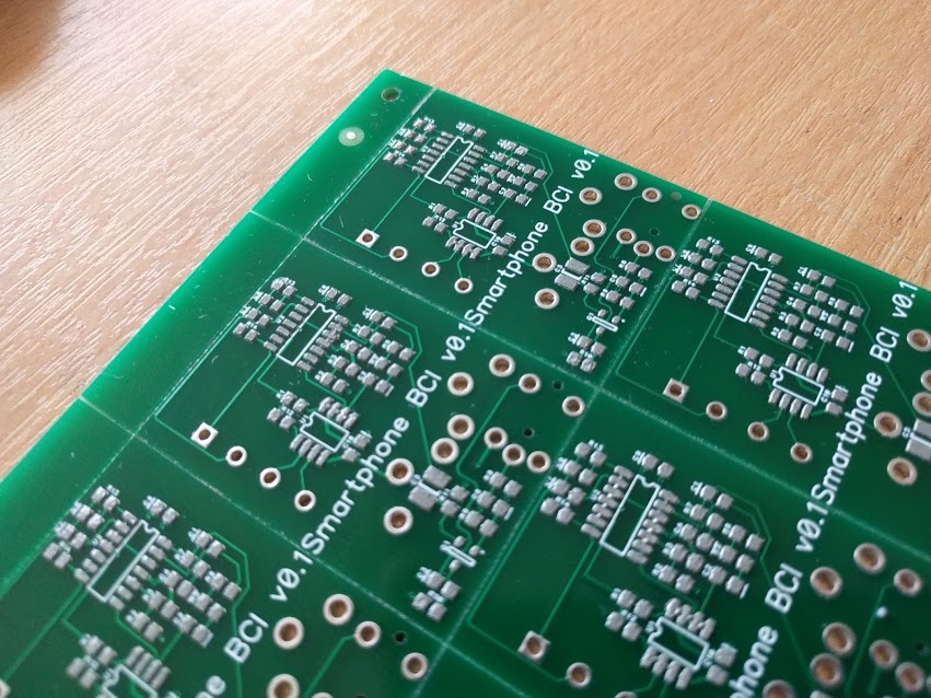
Kit v0.1
Each v0.1 kit should contain:
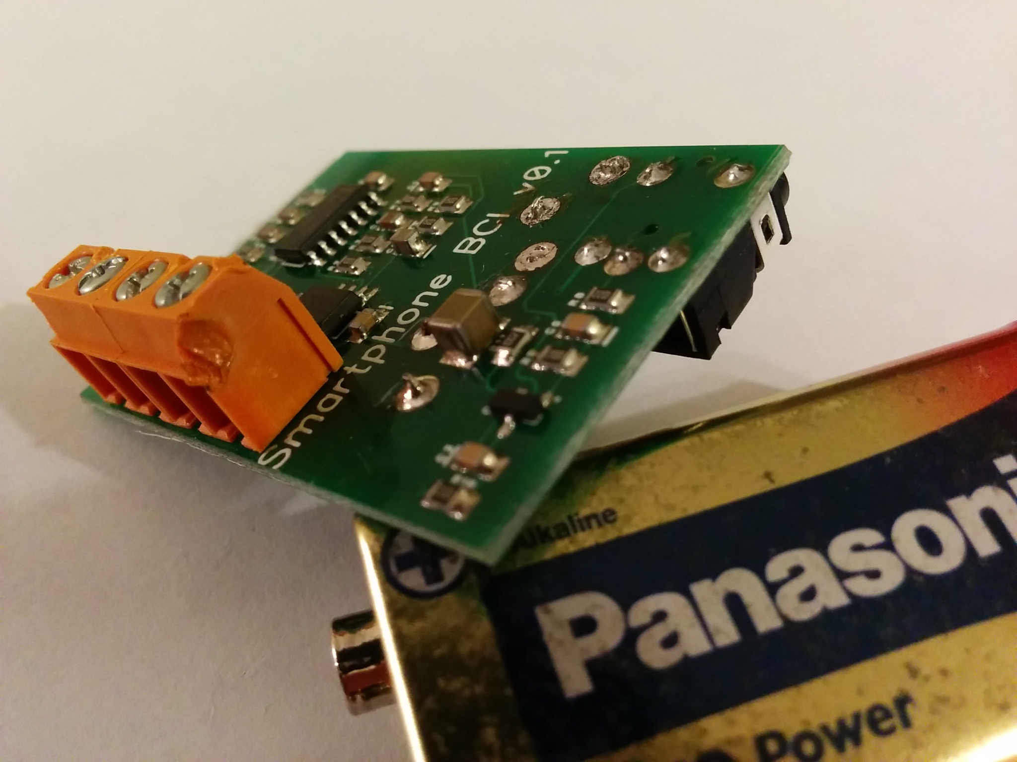
- 1x PCB
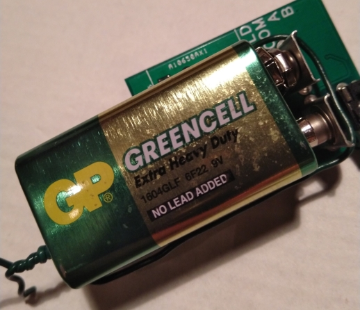
- 1x 9V battery
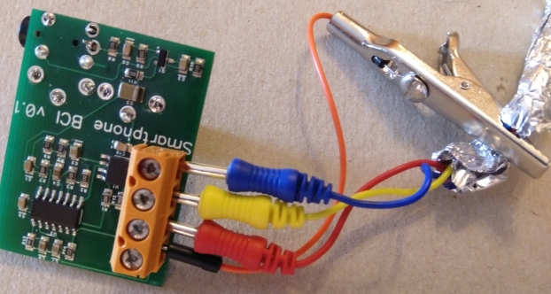
- 1x croc clip (for SHLD)
- 1x jumper wire (for SHLD)
- 1x 1m 3.5mm male-to-male audio cable (to attach phone to PCB)
- 3x electrodes (for A, B, COM)
- 2x alcohol swabs (to clean skin, electrodes following use)
- 1x resealable bag (to store Ten20 conductive gel)
- 1x bathing cap (separately)
- kitchen foil (separately; to SHLD electrodes)
Assembly
- Check if your kit is complete :)
- Braid/twist the three electrodes to reduce independent interference. Leave 20cms at the electrode end to allow flexible placement.
- Prepare to attach the electrodes to the screw terminal
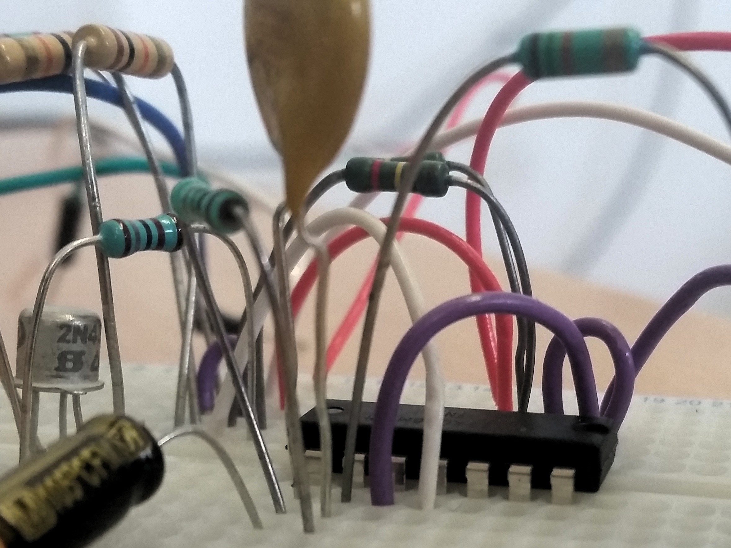
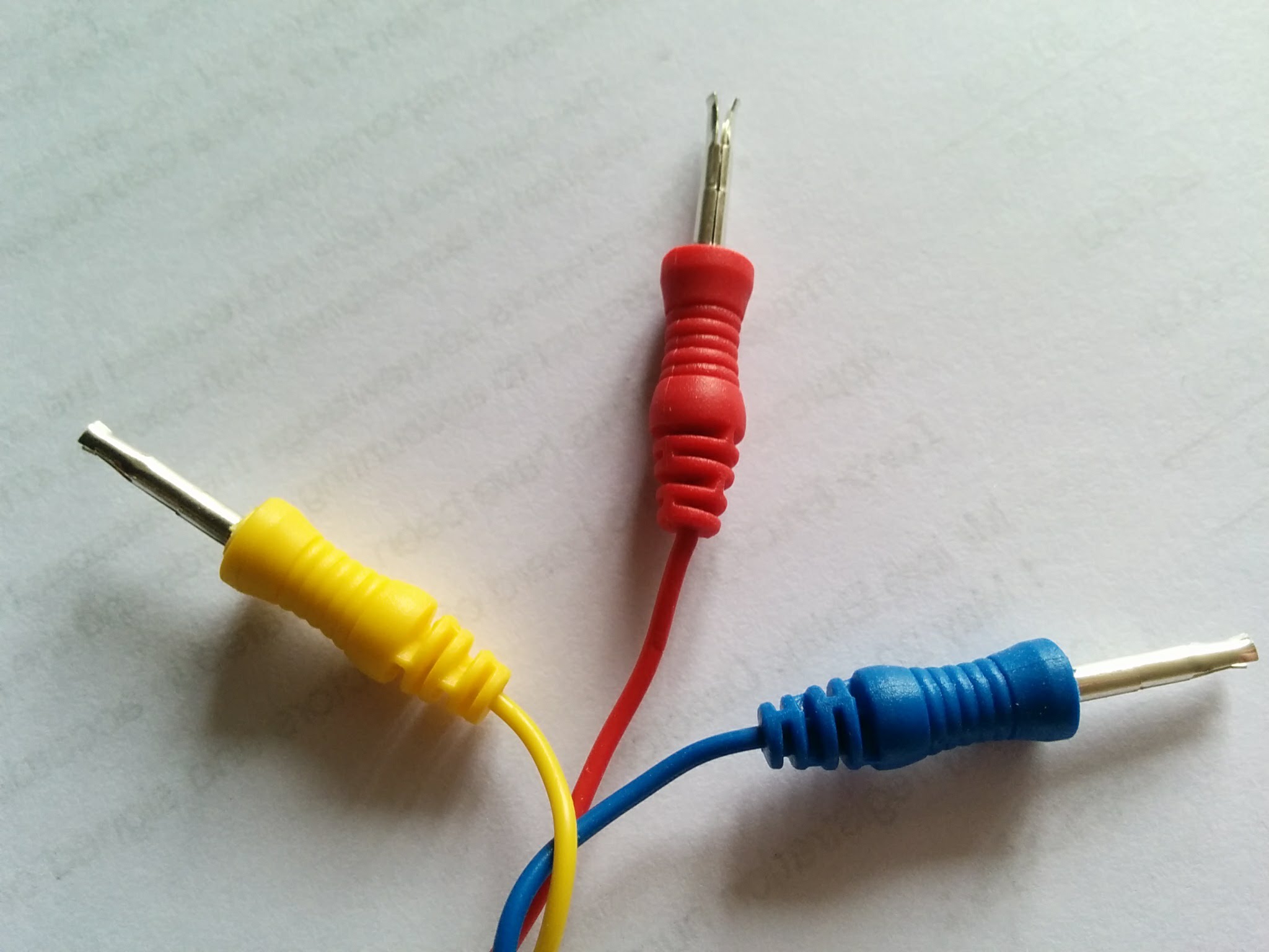
- high quality connection (recommended; see image with yellow, red, blue leads): gently strip the ends of the electrode terminals (NOT the wires, nor at the cup end), exposing the gold contacts; OR
- less antenna interference: cut the electrode wires short to mount the board (hot glue, etc.) directly to the cap
- Tightly wrap the braided part of the electrodes in tin foil to further reduce signal interference
- Attach the croc clip to the tin foil
- Attach the jumper wire to the croc clip and the SHLD terminal on the PCB
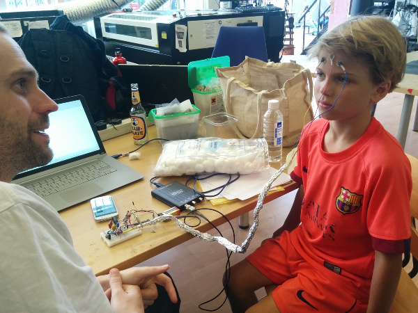
- Connect the electrodes to the screw terminal:
- A 1st electrode to scalp
- B 2nd electrode to scalp (order unimportant)
- COM ground to ear lobe or mastoid (if reading from back, e.g. o1 and o2) or middle of forehead (if from front, e.g. fp1 and fp2)
- 3.5mm audio cable into the audio jack of both the PCB and the smartphone/tablet/device (n.b. the audio cable can be temperamental - you can check it with a regular audio signal)
- Connect the battery. If your board has a blue screw terminal, check the positive and negative battery terminals: they are reversed on boards shipped through to 2020. Do not use the board in this configuration. If your board is correctly configured, the terminal labeled "+" will have flanges. If the battery terminals are reversed, attach the battery to the terminals the wrong way around, using twist ties or coated wire.
- using the board
- do NOT use icibici while your phone is connected to the mains (i.e. charging)
- fill the electodes' cups with conductive gel. (Do not use the cups as scoops: they will snap.)
- cleaning up after use
- unplug the battery
- clean the electrodes for re-use (the conductive gel promotes corrosion)
Blue screw terminal board and reversed current
Running the current in reverse through the boards (e.g. by attaching a battery directly to the battery terminals on a blue screw terminal board with reversed positive and negative battery terminals) should not harm the boards.
On 8 October 2017, we tested this by creating a simplified artificial brain by attaching an external signal generator to a positive and negative terminal separated by a saline solution in which the icibici electrodes were immersed: a functioning board should be able to read the signal crossing the saline solution. We first ran current backwards through the boards. We then re-inserted the battery the right way around and immersed the electrodes in the saline solution: they continued to correctly read the test signal.
In both early cases, the boards did not initially read the signals correctly. After we successfully read the signals on later boards that we had run in reverse, we re-tested the initial boards, and found that they did read the signals correctly. We have not sought to identify why our two initial tests were unsuccessful.
Is my board working?
As neural signals are very faint, it is common to be unsure whether the board is working properly. This section describes some simple 'sanity' checks.
- Attaching the board to the simplified artificial brain and signal generator, as described above, is the cleanest test we have found so far of a board's ability to receive signals.
- First test for stronger signals. One of the
easiest ways to do this is to connect the icibici to a computer and analyse the incoming signal
using something like Audacity or Matlab
(see the code here):
- electrocardiogram (ECG): attach the A and B electrodes to your chest, the COM electrode to an arm or leg, and see whether the signal looks like a heart beat;
- electromyogram (EMG): this site shows various locations for electrode placement. We have placed the A and B electrodes on the jaw (the COM on the neck) to pick up gnashing of teeth.
Hardware source files
Gerber, Eagle, diptrace, .asc (including PDF) files and BOM are here. We've not put an open-source licence on this yet, but please treat it as such.
Known issues
- Xiao Mi Redmi Note: basic Android APK can either generate tone, or receive signal from board, but not both at once.
- Huawei (2019): crashes on initially running the Unity SSVEP app; fine the second time.
To do
- see the Github Issues tracker here
The Software
Android diagnostic APK
The basic Android diagnostic app is available for download here.
Sanity Check
After assembling the hardware, install the APK and connect the kit to do a sanity check:
- Install the app on the phone
- Connect the battery to the circuit
- Ensure that the phone is NOT connected to the mains
- Connect the jack from the circuit to the phone
- Open the app
- Press "Play"
- if the app crashes pressing play (e.g. in Android 6), you need to grant permission the the app to access the microphone in settings/apps/smartphone-bci
- Slide until you get to a graph called 'sanity check'
- Do not hold the circuit with your hands, as your body acts as ground
- You should see two peaks in the graph; one around 0-1 Hz (carrier signal), one around 50Hz (mains)
Experiments
Placing the electrodes using the 10-20 system:
- Use alcohol to swab the area where the electrodes will be placed.
- Fill the electrode cup with conductive gel before placement and clean them after the experiments to prevent corrosion
- If measuring from o1 and o2, place COM electrode on ear (best: avoids muscular signals) or side of neck
- If measuring from fp1 and fp2, COM can be placed on the center of the forehead
Experiments with the completed kit:
- the Android app's "sanity check" to detect the 1kHz carrier signal and 50Hz mains
- the first plot titled "Spectrum" might show changes when winks, blinks, jaw movements are performed
- alpha waves (7.5 - 12.5 Hz) from o1 and o2 or (to a lesser extent) fp1 and fp2 when user's eyes are closed
- Swipe to the next graph: it displays the power of your alpha band over time.
This value corresponds to a moving average, so it may take some time to settle. - mu waves (7.5-12.5 Hz, esp. 9-11Hz) from c3, c4 or even cz when user is completely immobile
In the near future !
- Swipe to the next graph: it displays the power of your alpha band over time.
- SSVEP: peaks at the frequency of an observed flashing stimulus from o1 and o2
- Experiment with placing the PCB on a table, holding it in your hand, etc. Where do you get the better signal?
Unity text entry
v0.16 (Aug 2019)
- The larger the screen on your device, the better this works.
- Check out the github page for a complete description and Android download.
- To use the iOS version (available as a beta on Testflight) sign up at https://testflight.apple.com/join/QYT2bQc4.
- The app can also be run in the Unity emulator.
- A simple test: select 'SSVEP Keyboard'/'Key Toggle' and manually cover either 'yes' or 'no' so that the user can only see one flickering target. Does the app reliably identify it?
etc.
- 5 Nov 2017: read Robert Oostenveld's review of icibici
The team
The team is composed by an amazing and heavily heterogeneous group of people that have voluntarily contributed in many different ways. This project would not have been possible without input and help from all the fellow travellers on this journey so far. In no particular order, many thanks to:
- Graeme Hattan
- Jon Scott
- Nick Johnson
- Colin Rowat
- Tommy Drews
- Felix Drews
- Ryan Lintott
- Javier Asensio Cubero
- Jesus Manzanares Artolazabal
- Andrew Vladimirov
- Seb Wills
- Bob Kemp
- John Mitchell
- Marco Datola
- Bethel Osuagwu
- Frank Johnson
- Martin U.
- Richard Graham
We've received more support anyone could hope for from NeuroTechX and their slack as well as the London Hackspace
This is a living project and we're still looking for people to contribute in whatever way they want to, please join the icibici Google Group.